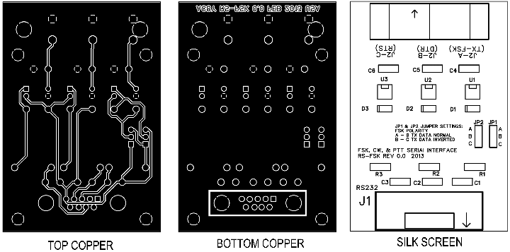
Many popular FSK software packages can be configured to send FSK keying data through an RS-232 serial port. With a suitable interface, this signal can connect to the FSK input of an HF transceiver to produce spectrally pure FSK RTTY signals. The project described here is intended to be an easily constructed FSK interface circuit.
The RS232 communications standard defines the Mark signal voltage -15 to -3 volts, the Space signal is +3 to +15 volts. The interface is designed to be compatible with signals within the defined voltage range. The dimensions of the two connectors are critical for proper mounting on the prescribed circuit board. Otherwise, the components are fairly generic. All components were available from Mouser Electronics.| Reference | Quantity | Manufacturer | Part Number | Description |
| C1 – C6 | 6 | Vishay | D103M29Z5UH6UJ5R | Ceramic Disc Capacitors .01uF |
| D1 – D3 | 3 |
Fairchild Semiconductor | 1N914B | Diode, Rectifier |
| J1 | 1 | FCI | 10090099-S094XLF | D-Sub Connector DB9P |
| J2 | 1 | Kobiconn | 161-4222-E | Triple Phono Connector Red, Green, Blue |
| JP1, JP2 | 2 | FCI | 68786-202 | Jumper Shunt |
| JP1, JP2 | 1 | 3M
Electronic Solutions |
961116-6404-AR | 16 Pin Header, Cut to Length |
| R1 – R3 | 3 | Xicom | 293-1.5K-RC | Resistors, Through Hole 1.5K ohm |
| U1, U2, U3 | 3 | Fairchild Semiconductor | FOD852300 | Transistor Output Optocoupler |

CONFIGURATION
With the JP1 & JP2 jumpers in the NORMAL position, a negative voltage on the RS232 TX pin will assert the J2-A FSK output. For positive RS232 TX pin keying, the jumpers should be installed in the INVERTED positions.
Note: Proper operation has been verified using MMTTY and a Ten-Tec Orion-I with the jumpers in the INVERTED position. Selecting the “Invert Logic” option on MMTTY Set-Up TX option tab inverts the polarity of the PTT signals.
EMI, RFI SUPPRESSION
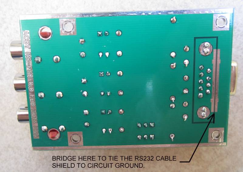
C1 through C6 are intended to minimize the effects of RF pick up on the data or keying lines. The outer ring of the output connectors is tied to the circuit ground layer. The DB9 connector shell is isolated from the circuit ground. The RS232 cable shield could form a ground loop if the connector shell was tied to the circuit ground. But leaving the RS232 cable shield floating at one end could also cause EMI in some situations. For that reason, an unmasked area on the bottom side of the board was provided to allow the connector shell to be tied to circuit ground if necessary. SMT capacitors could be installed to provide RF but not DC grounding of the shield.
The measured turn-on delay of the optical isolators is about 2 µs and turn-off delay is about 4 µs. Those values would not be significant for normal data rates but since the circuit relies on the radio's internal pull-up resistors to pull the signal back high after turn-off, the rise-time is much more significant. With 0.01 µF capacitors installed at C4, C5, & C6, the rise time was measured at 120 µs which could be a problem for TTY data rates over 1 kb/s. At 45 or even 100 baud, that is insignificant but if the circuit is used for high rate data, the output capacitors should be removed or replaced with smaller values. For HF RTTY and Morse, the Fairchild FOD852 optocoupler used here is adequate. For other applications a faster unit may be required.
ENCLOSURE
No enclosure is necessary for proper operation. Grounded copper layers provide sufficient immunity from RF coupling. Adding an enclosure results in a nicer appearance and improves durability but at least doubles the assembly time and cost of the project.
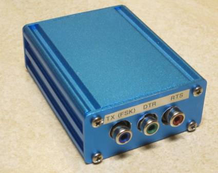
The
PC board dimensions were intended to match the BEX
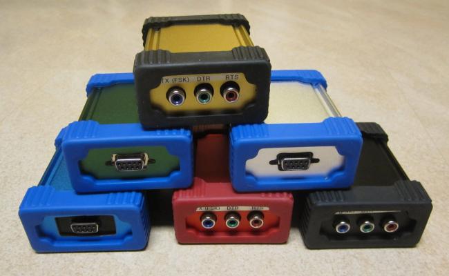
Series 1 1.18" H x 2.5" W x 3.15" L extruded aluminum
enclosures made by Box
Enclosures. These enclosures come in various colors and optional rubber
end
caps are available. Scaled drill and cutout templates can
be downloaded here.
Shipping might be cheaper from Newark
Electronics.
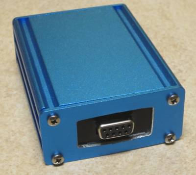
A
DB9 hole punch could also be used to save a lot of time nibbling the
rectangular hole for the RS232 connector but could also allow the
connector shell to contact the metal end plate.
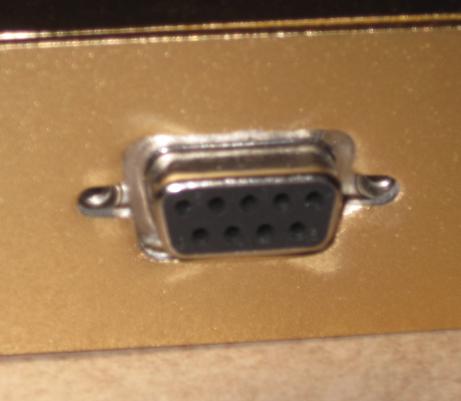
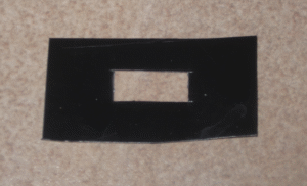
If electrical isolation of the RS232 connector shell is desired, some sort of insulator is needed.
|
|